Got a request for a quick how-to on installation.
This is a U.S. version, Rev. 2 installed in a standard 110v 2-phase panel. Probably goes without saying, but this requires you to be in proximity to a lot of electricities that can do you great harm. If you aren't comfortable working around many electrons, I'd recommend turning to a professional. The safest bet is to pull the mains and work on the dead side of the panel.

- Aeotec DSB28-US
- IMG_2037.JPG (88.47 KiB) Viewed 13120 times
Here's what's in the box.

- Aeotec DSB28-US unboxed.
- IMG_2040.JPG (129.78 KiB) Viewed 13120 times
Typical U.S. 2-phase panel--rust and all. You'll notice three thick black cables entering through the top of the panel. These are the two phases and neutral.
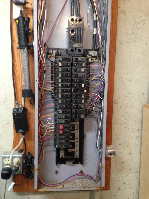
- Typical U.S. 2-Phase panel.
- IMG_2046.JPG (208.43 KiB) Viewed 13120 times
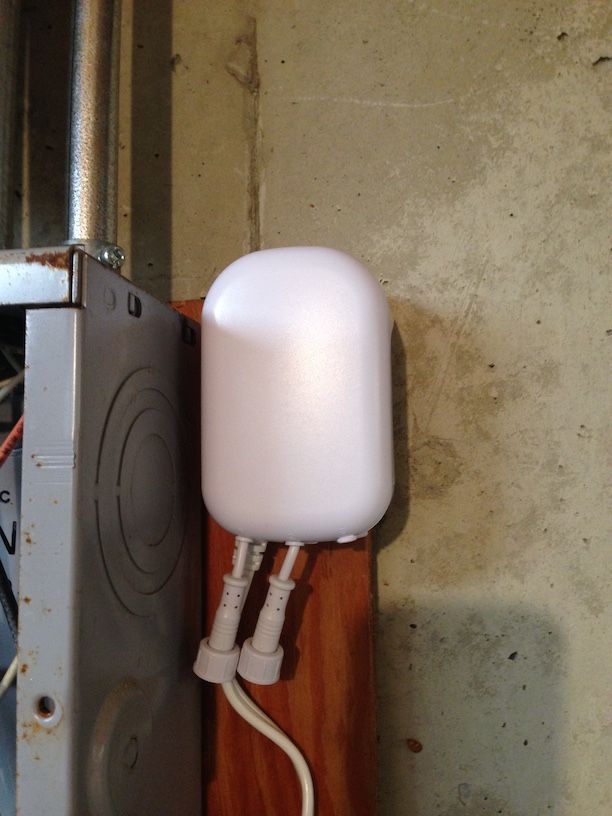
I placed the transmitter outside the panel. You'll notice that this version has two connectors for two clamps (one clamp for each phase.) The connectors are weather resistant if mounted in this orientation. Indigo will provide a facility for three clamps--but understands that only two are connected.
- DSB28-US mounted externally.
- IMG_2050.JPG (159 KiB) Viewed 13120 times
The two clamps installed. The clamps go around the wires. There's no need to cut in or splice any wires. If you haven't pulled the mains, there's a lot of electricity in these wires.
Be careful. Know what you're doing.

- Clamps attached to the 2 phases.
- IMG_2051.JPG (165.38 KiB) Viewed 13120 times
The clamps must be installed in a specific orientation. This orientation depends on the individual application. What's important is knowing which phase will provide power to the DSB-28. In my case, it's the phase on the left. The arrow goes towards the utility on this phase (the phase that provides the power to the unit), and away from the utility on the other phase.

- Clamp orientation indicator.
- IMG_2042.JPG (107.94 KiB) Viewed 13120 times
I used a standard Romex clamp (and numerous Monoprice wire ties) to hold the wires.

- DSB28 wires exiting the panel.
- IMG_2053.JPG (148.27 KiB) Viewed 13120 times
The final result. The unit draws its power from a standard power cord which in my case runs to an outlet mounted to the other side of the panel. You could cut the power cord and connect it straight to the mains, but I saw no need. There's a fair bit of slack in the wires which would allow for the transmitter to be mounted a good bit further away from the panel if interference is a problem. Interference wasn't a problem for me at all. The inclusion/exclusion button is on the back of the unit. It slides easily out of the mounting plate.

- Final placement.
- IMG_2054.JPG (149.88 KiB) Viewed 13120 times
That's it. The entire thing from start to finish was less than an hour.